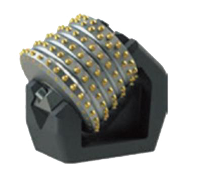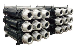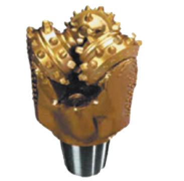
After the raise-boring machine completes the pilot hole construction, thesmall-diameter pilot hole is enlarged to the designed shaft size by back reaming.
1. Rock crushing and cutting: The cutter head equipped with the carbide rollercutters or picks crushes the rock mass by rotation and axial pressure.
2. Shaft size control: The diameter of the cutter head directly determines the fin-ished shaft size and must strictly conform to the design specifications.
3. Cuttings discharge assist: When the cutter head rotates, the cuttings fallthrough the slag discharge chute or flushing system on the cutter head into thelower tunnel.
4. Power transmission and load bearing: The cutter head is connected to therotary drive of the drilling rig through the drill rod to bear extreme torque, axialtension, and vibration.
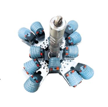
Cutter head configuration table (OEM)
| Cutter head diameter (mm) |
Tension rod diameter (mm) |
Type of cutter head | Component | Number of complete sets | Number of roller cutters |
| Φ900 | Φ190 | Integral | 1 | 4 | |
| Φ1000 | Φ190 | Integral | 1 | 6 | |
| Φ1500 | Φ214 | Integral | 1 | 8 | |
| Φ2000 (Φ1470) | Φ214 | Combined | Cutter box | 1 | 12 |
| Segment | 4 | ||||
| Φ2500 | Φ254 | Combined | Cutter box | 1 | 14 |
| Blade | 2 | ||||
| Φ3000 (Φ2000) | Φ254 | Combined | Cutter box | 1 | 20 |
| Segment | 8 | ||||
| Combined | Cutter box | 1 | 18 | ||
| Blade | 2 | ||||
| Φ3500 | Φ286 | Combined | Cutter box | 1 | 22 |
| Blade | 2 | ||||
| Φ4000 | Φ327 | Combined | Cutter box | 1 | 22 (14 inch) |
| Blade | 2 | ||||
| Φ5000 | Φ350 | Combined | Cutter box | 1 | 28 (14 inch) |
| Blade | 2 | ||||